

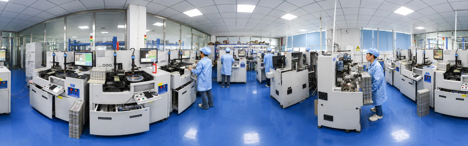
Injection Molding Machine
Dec 15, 2025
Leave a message
Injection Molding Machine
Walk into any plastics factory floor and the rhythmic clunk-hiss of injection molding machines sets the tempo. These workhorses push molten polymer into steel cavities thousands of times a day, spitting out everything from bottle caps to automotive dashboards. The technology traces back to modified die-casting equipment from the 1800s, though the real breakthrough came when German engineers figured out how to use a rotating screw instead of a simple plunger. That screw design from the 1950s remains the backbone of modern machines.

How the Process Actually Works
The barrel sits horizontal on most machines, wrapped in heater bands that bring temperatures anywhere from 180°C to over 300°C depending on the resin. Pellets drop from the hopper into the feed throat. Here's where the screw earns its keep-as it rotates, flights along its length grab material and drag it forward. The combination of barrel heat and mechanical shear from the screw action melts the plastic progressively. By the time material reaches the front, it's a homogeneous melt ready for injection.
During plasticizing, the screw backs up as molten material accumulates ahead of it. Back pressure applied through the hydraulic system controls how much resistance the screw feels while retracting. Too little back pressure and you get inconsistent melt. Too much and you risk degrading heat-sensitive materials. Getting this balance right separates a quality part from scrap.

Once enough material collects for the shot, the screw stops rotating. The machine waits for the signal that cooling has finished on the previous part. Mold closes, clamp tonnage builds, and the screw rams forward. Injection happens fast-fill times under two seconds are common for small parts. The melt rushes through the nozzle, down the sprue, through runners, past the gate, and into the cavity.
Pack and hold phases follow immediately. The screw maintains forward pressure to compensate for shrinkage as plastic cools against the cold mold steel. Holding continues until the gate freezes off. At that point, no more material can enter the cavity regardless of pressure applied. The machine switches to plasticizing the next shot while the part continues cooling.
Cycle ends when the part has solidified enough to eject without warping. Mold opens, ejector pins fire, part drops. The whole sequence might take 15 seconds for a thin-wall container or several minutes for a thick structural component.
Machine Hardware
Clamping systems come in three flavors. Toggle machines use mechanical linkages that multiply force near the closed position-great efficiency but the mechanism needs regular greasing and eventual bushing replacement. Direct hydraulic machines push the moving platen with a large-bore cylinder. Simpler mechanically, though they burn more oil moving all that fluid. Hybrid configurations use servomotors for positioning with hydraulic assist for final clamping force.
Clamp tonnage sizing follows a basic rule: projected part area times cavity pressure. A 100 square centimeter part running at 500 bar cavity pressure needs 50 metric tons minimum. Most shops add 10-20% safety margin. Undersized clamp tonnage shows up immediately as flash at the parting line-thin fins of plastic squeezing out where mold halves meet.

The injection unit bolts to the stationary platen side. Barrel diameter and screw L/D ratio determine shot capacity and plasticizing rate. General-purpose screws run 20:1 length-to-diameter with a compression ratio around 2.5:1. Barrier screws improve melt quality for semi-crystalline materials. Mixing sections help with color concentrate dispersion.
Servo-hydraulic drives have largely replaced fixed-displacement pumps on newer equipment. The motor only runs as fast as needed for the current phase, cutting energy consumption 30-50% compared to older machines running constant rpm with flow dumped over relief valves.
Running the Machine
Temperature setpoint selection starts with the resin manufacturer's processing data sheet. Zone temperatures typically step up from rear to front, with the nozzle running hottest to prevent freeze-off. For polypropylene, rear zone might sit at 190°C, middle zones at 210-220°C, front at 230°C, and nozzle at 240°C. Actual melt temperature measured with a pyrometer often runs 10-15 degrees higher than the front zone setpoint due to shear heating.
Screw speed during recovery affects both cycle time and melt quality. Faster rotation shortens recovery but generates more shear heat. Heat-sensitive materials like PVC and POM need slower speeds. The screw should finish plasticizing before the cooling timer expires-otherwise the screw waits idle and cycle efficiency drops.

Injection velocity profiles deserve attention on complex geometries. Slow initial speed prevents jetting through small gates. Mid-stroke acceleration fills the bulk of the cavity quickly. Final deceleration avoids pressure spikes at pack transition. Modern controllers handle multi-stage velocity with precise switchover points based on screw position.
Pack pressure typically runs 60-80% of peak injection pressure. Duration depends on gate dimensions and material. Small gates freeze in 2-3 seconds. Submarine gates on thick parts might need 8-10 seconds. Insufficient pack time shows up as sink marks over ribs and bosses.
Troubleshooting Common Defects
Short Shots
Short shots mean plastic didn't reach all corners of the cavity. Check that shot size exceeds part weight plus runner weight by at least 10-15%. Verify vents aren't blocked by residue or flash. Increase injection speed or pack pressure if barrel capacity checks out.
Flash
Flash around the parting line points to either insufficient clamp tonnage or worn mold surfaces that no longer seal properly. A quick test: run a series of shots while incrementally reducing clamp force until flash appears, then set tonnage 15% above that threshold.
Burn Marks
Burn marks near the end of fill indicate trapped air igniting under compression. Diesel effect, the old-timers call it. Add vents where burns occur or slow down injection velocity to give air time to escape through existing vents.
Weld Lines
Weld lines form where flow fronts meet. They're structurally weak and sometimes visible on cosmetic surfaces. Adjusting gate location or adding overflow wells can push weld lines to non-critical areas. Higher melt temperature improves weld line strength by allowing better molecular entanglement before freezing.
Where These Machines End Up
Automotive consumes the largest share of injection molding capacity globally. A single car contains 30-40 kg of injection molded parts-bumper fascias, instrument panels, door handles, mirror housings, hundreds of clips and fasteners.

Electronics housings push tight tolerances and thin walls. Phone cases, laptop shells, and remote controls demand cosmetic surfaces free of sink, flow lines, or gate vestiges. Medical device molding adds material traceability and cleanroom requirements on top of dimensional precision.
Packaging runs high-cavitation molds at blistering cycle times. Closure molds with 96 or 128 cavities cycling every 4-5 seconds need machines built for sustained high-speed operation.
Smaller operations find steady work in custom molding for niche applications. We see consistent demand from companies producing RFID keyfob housings and access control components-these parts need precise cavity dimensions to seat antenna coils and transponder chips correctly. Livestock identification presents another specialty segment; RFID ear tag suppliers require overmolding capability to encapsulate electronics in a single weatherproof shell. Credential manufacturers sourcing RFID card production look for molders comfortable with thin-wall inserts and secondary assembly operations.
Practical Considerations for Production
Machine hour rates vary wildly based on tonnage and market. A 150-ton machine in a competitive region might bill out at 25-35 dollars per hour including operator. Larger tonnage commands higher rates, though efficiency gains sometimes offset the premium.
Energy costs matter more than many shops realize. A 500-ton hydraulic machine running three shifts draws 40-50 kW averaged across the cycle. Servo-hydraulic retrofits pay back in 18-24 months at current electricity prices in most markets.
Mold maintenance directly impacts part quality and machine uptime. Scheduled cleaning of vents, inspection of core pins, and verification of cooling channel flow should happen at defined shot intervals. Reactive maintenance after quality defects appear costs far more than preventive programs.
Material handling deserves attention proportional to resin sensitivity. Nylon, PET, and polycarbonate need drying to specific moisture levels or hydrolytic degradation ruins mechanical properties. Conveying systems should avoid metal contamination that damages screw and barrel surfaces.
Automation additions-robotic part removal, automated insert loading, vision inspection-make sense at volumes where labor savings exceed equipment lease costs. Low-volume custom work rarely justifies full automation, though simple sprue pickers improve cycle consistency by removing operator variability from mold open time.
Send Inquiry